|
|
By Dominic Vautier
orig 11/2018
update 1/2019
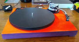
I began collecting parts for my turntable some time ago because I wanted to come up with a unit that played as good as the high priced ones but I also wanted a pretty simple one that had just the features I liked and that were useful. It needed an isolated motor and basic arm functions, but it did not need all the other stuff that usually comes with high-end units. It also had to have standard head-shells since all my carts use standard mounts. The arm needed queuing, anti-skate, stylus weight and plinth adjustment, all the really basic stuff but nothing else.
The plinth adjustment was for VTA (vertical tracking angle) which I understand is not a big consideration but overlooked and sometimes hard to measure without a computer microscope. I have carts of different sizes so VTA does matter and it takes a lot of fooling around with shims to get it right.
Mostly I wanted simplicity. I did not want any of the elaborate mechanisms involved in arm return. I don't even want an on/off switch. My power bar does that along with the preamp. Just taking a look under my Technics with all the leavers and switches is truly a frightening experience which I would think requires at least two degrees in mechanical engineering to understand. My Technics is quite a fine unit but suffers from low rumble and sometimes returns before the last song finishes. Other than that it was a very tolerable machine by any standards.
It seems that all the TTs I have ever owned had something or other about them that I did not like. Rumble and early return may be just some of the typical problems of direct drive and automatic return TTs, but there seems to be no way to get away from some rumble or motor noise unless the DC motor is physically detached and away from the unit itself and all power supplies are some distance away.
Here is a summary of what I like to have in a turntable and why I built my own.
This description is intended to help people who may want to make a
turntable from components and have tone-arms, motors and platters and don’t know quite how to begin. You have to
start by getting the kind of parts you want. I got a motor,
belt, power supply and platter from an old Pro-ject turntable. Pro-jects have very good motors but I
wanted a different tonearm. I got a pretty good one from
| Arm length | The APPARENT arm length from tracking pivot to the stylus. There is about a 26 degree curve in most arms. |
| Arm pivot | The point above the deck where the arm pivots up and down. |
| Head-shell | Standard straight head-shell |
| MM | Everything described here is in millimeters |
| Platter | The thing that turns around |
| Plinth | The (in this case, adjustable) surface of a tone-arm that supports queue lever and lock. It changes the stylus attack angle. |
| PtoS | Tracking pivot distance to spindle. Here arm pivot=tracking pivot which is different from up and down pivot or arm pivot. |
| shell surface | Area of the head-shell that mounts the cartridge |
| Spindle | The center hole where the platter spins. |
| Table | The surface body that holds the platter and tone-arm. The motor is not part of the table. |
| Tracking Pivot | The point at witch the tone-arm pivots horizontally to follow record grooves. The industry refers to this simply as pivot but there are two pivots in a tone-arm. Both are important. |
| VTA | Vertical tracking angle. The stylus angle to surface of record. The optimum is around 90 degrees but depends on the cartridge. |
When you get a brand spanking new tone-arm it has 5 wires that go down the tube and through the plinth, oftentimes these wires are not woven. You can find this out by looking at the wires as they run from tube to plinth. Woven wires are more resistant to EM noise. If you decide to weave the wires it's easier to do as long as you have the arm unmounted. It's harder to do later because you have to unsolder the wires from the bus.
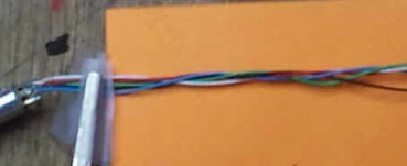 Take the wires out by removing the small screw
under the headshell socket and pulling slowly. Tie a string to the
other end of the five wires for easier re-install. Use a 5-way
flat weave but don't weave too tight. After reinstalling check
continuity and interference.
Take the wires out by removing the small screw
under the headshell socket and pulling slowly. Tie a string to the
other end of the five wires for easier re-install. Use a 5-way
flat weave but don't weave too tight. After reinstalling check
continuity and interference.
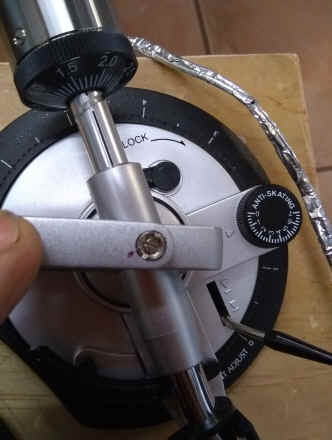
 A factory tone-arm should have its bearings checked.
It's easier to do this before mounting. I think they are sometimes shipped loose
for safety.
If you can feel a wiggle the bearing needs to be tightened. If you can’t feel a wiggle at all it may be OK but you should
check it anyway (described below). If the bearings are in need of adjustment be sure to MARK the
location of the center screw FIRST and then release the lock nut one half
turn. Then tighten the center screw observing how many degrees the
center screw can be tightened to achieve a very soft snug. Then back it off. The
rule is 30 to 40 degrees backoff or about 1/8th turn, no more.
Hold the center screw in position while tightening lock nut. You don’t have to tighten much.
Tightening the set screw can change the snugness. Test again for wiggle. After moderately setting the lock nut It should not come loose again. Mark the final position.
A factory tone-arm should have its bearings checked.
It's easier to do this before mounting. I think they are sometimes shipped loose
for safety.
If you can feel a wiggle the bearing needs to be tightened. If you can’t feel a wiggle at all it may be OK but you should
check it anyway (described below). If the bearings are in need of adjustment be sure to MARK the
location of the center screw FIRST and then release the lock nut one half
turn. Then tighten the center screw observing how many degrees the
center screw can be tightened to achieve a very soft snug. Then back it off. The
rule is 30 to 40 degrees backoff or about 1/8th turn, no more.
Hold the center screw in position while tightening lock nut. You don’t have to tighten much.
Tightening the set screw can change the snugness. Test again for wiggle. After moderately setting the lock nut It should not come loose again. Mark the final position.
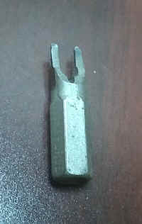
You may have to make your own spanning tool for the locknut. I took a flat blade and ground it to spec.
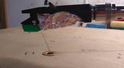
I calculated the PtoS on my new table at 222 mm. I did this by taking the average of the three head-shells I have and measuring the arm length which came in at 234 mm. This gave me an arm length of 228 mm to 238 mm. With this I can get an overhang of from 10 to 20 mm.
My Technics has a slightly longer 230 mm null point adjusted arm length, a 213 mm PtoS and therefore a 17 mm overhang but the arm angle is less so I didn’t need 17 mm overhang. I think that the overhang depends on some other things but it is usually around 1/13th of PtoS.
The overhang range has to be within a certain tolerance because standard turntables often are designed to use just one set of null points. I needed a unit that could adjust both overhang and cartridge angle to accommodate any set of null points, even my own. see : null-points.
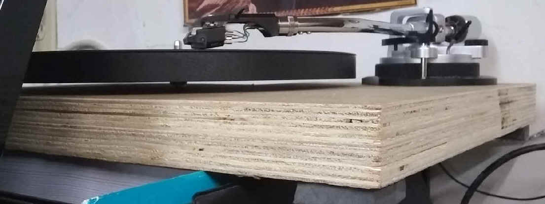
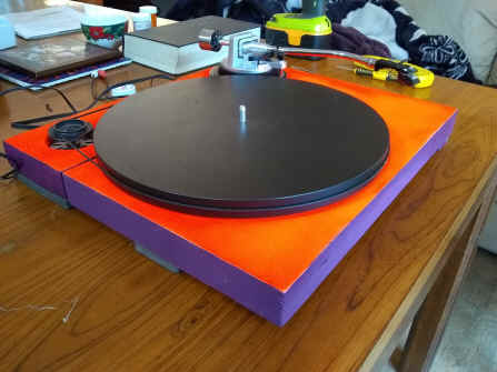
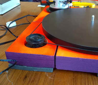
The table was eventually cut to 410 by 355 mm. The spindle hole is 160 mm in from the front and left. The spindle to motor was 180 mm so when I cut out the motor block it allowed a 4 mm rubber buffer. I used some measurements from my old Pro-ject TT to determine this the optimum distance from motor to spindle as well as height.
I cut my table from 2 pieces of 10-ply and pressured glued them together to make a solid 1 ½ inch slab. I then drilled out the pivot hole and cut a larger hole for the motor. It was only later after I tested that I cut out the motor block. I tested the RPM again and got exactly 100 over 3 minutes.
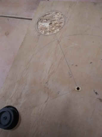 I first
installed the spindle at 165 mm from the front and 165 mm from the
left. From there I measured the motor location being 180 mm and the
arm at 220 mm away from the spindle. I then measured and installed the
motor then began drilling out clearance for the tonearm base. before
drilling I calculated the distance and measured overhang.
I first
installed the spindle at 165 mm from the front and 165 mm from the
left. From there I measured the motor location being 180 mm and the
arm at 220 mm away from the spindle. I then measured and installed the
motor then began drilling out clearance for the tonearm base. before
drilling I calculated the distance and measured overhang.
I put two marks at 12 and 20 mm past the spindle. I then used my AT green and my M97e cartridge to make sure they both fall within the overhang. I really needed to get this part right.
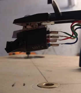
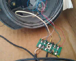
There are five wires to a tone-arm, two signal wires, two signal grounds and a chassis (chasy) ground. The chassis ground extends from the cartridge base and head-shell base through the arm, shielding the other wires up to the preamp. The chassis ground is meant to protect against outside electrometric interference and is very much needed since cartridge signals are so weak. These three grounds are all separate and should never contact each other. The two signal grounds are totally dedicated to signal.
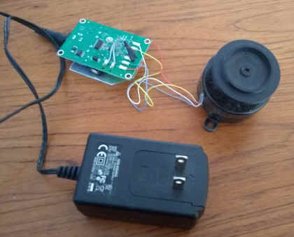
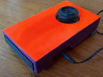 Here
is my motor, regulator and power supply. This is an Hysteresis
synchronous motor and there is no speed adjustment for a very good reason.
Speed adjustments involve variable capacitor circuitry which can change
based on temperature, elevation and air pressure. Having such a
feature is not reliable or even particularly desirable. A motor speed based
on CPM (cycles per minute) is very reliable
because so many electronics on any power grid depend on a precise 60 CPM or
50 CPM in other places.
Here
is my motor, regulator and power supply. This is an Hysteresis
synchronous motor and there is no speed adjustment for a very good reason.
Speed adjustments involve variable capacitor circuitry which can change
based on temperature, elevation and air pressure. Having such a
feature is not reliable or even particularly desirable. A motor speed based
on CPM (cycles per minute) is very reliable
because so many electronics on any power grid depend on a precise 60 CPM or
50 CPM in other places.
 The
motor was tested and then the motor block was cut out from the deck.
Padding was glued to the sides so it would never come directly in contact
with the rest of the deck.
The
motor was tested and then the motor block was cut out from the deck.
Padding was glued to the sides so it would never come directly in contact
with the rest of the deck.
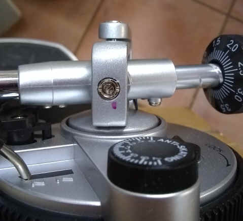
For adjusting the arm the table has to be absolutely flat and the tracking pivot axis has to be perpendicular. There should be no wiggle in the bearings at this point.
To test the arm pivot bearing (the up-down motion), bring the arm to zero weight on the counterbalance and move it to a neutral position just off the platter. The stylus should be at record play level. Gently tap it up. The arm should oscillate at least 5 times before coming to rest again at record play level. If it does this and it has no perceptible wiggle, it is properly adjusted.
To test the tracking pivot bearing (back-and-forth motion), bring arm to slightly less than zero which raises it above the platter by 10 mm or so. Put on about 1 gram antiskate. Give the arm a very gentle nudge inward. It should glide inward half way then return to start of record. Take off anti-skate. Give the arm another gentle nudge. It should glide to the center stop and slowly glide back. If you have an auto return this may not work because the arm can get stuck in the auto return mechanism. But if it glides in its adjusted OK.
Plinth adjustment allows easy vertical tracking angle adjustment. The mounting surface on a
head-shell may not be parallel to the record
surface in the play position or the arm pivot may be too high or too low when
the stylus contacts the record. The distance from deck to record surface may also
be different. My arm has an adjustable plinth of from 43 mm to 53 mm above the
table and my
platter was 28 mm above the table. This
gave me about 18 to 28 mm variance for the distance from the center of the tone-arm
tube to the stylus. The end
result of plinth adjustment is to get VTA as close as
possible. Consider the standard
head-shell in the diagram.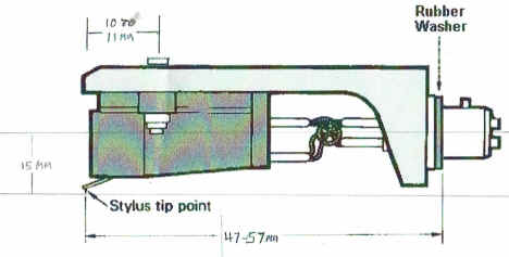
Several conditions play a part in VTA, the angle of the head-shell to the record surface, the distance from head-shell mounting surface to playing surface, and the angle of the stylus to the cartridge mounting brackets. These are a lot of considerations. I do notice that VTAs vary with cartridge size, cartridge mounts and stylus. An easy way to get it right is to mount the cartridge, set it on a record and adjust the plinth. Use a computer microscope if you have one to check it. I noticed that the plinth should more often be adjusted to record surface rather than platter surface.
.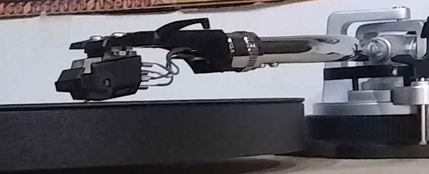
Here my Shure M97x is close. Notice the plinth
is adjusted at platter height. It needed to come up some more.
There are other adjustments that take more time such
as null points. Here is my discussion of null point
adjustment.
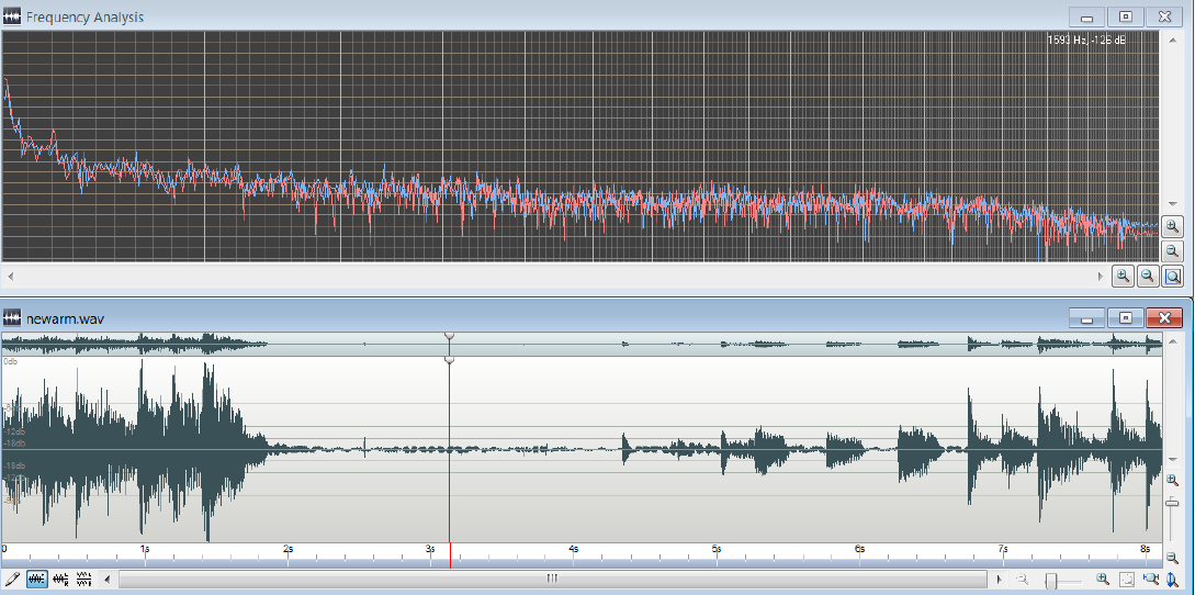
Below is a sample taken from my new turntable. It shows no rumble. You can hear the recording here.
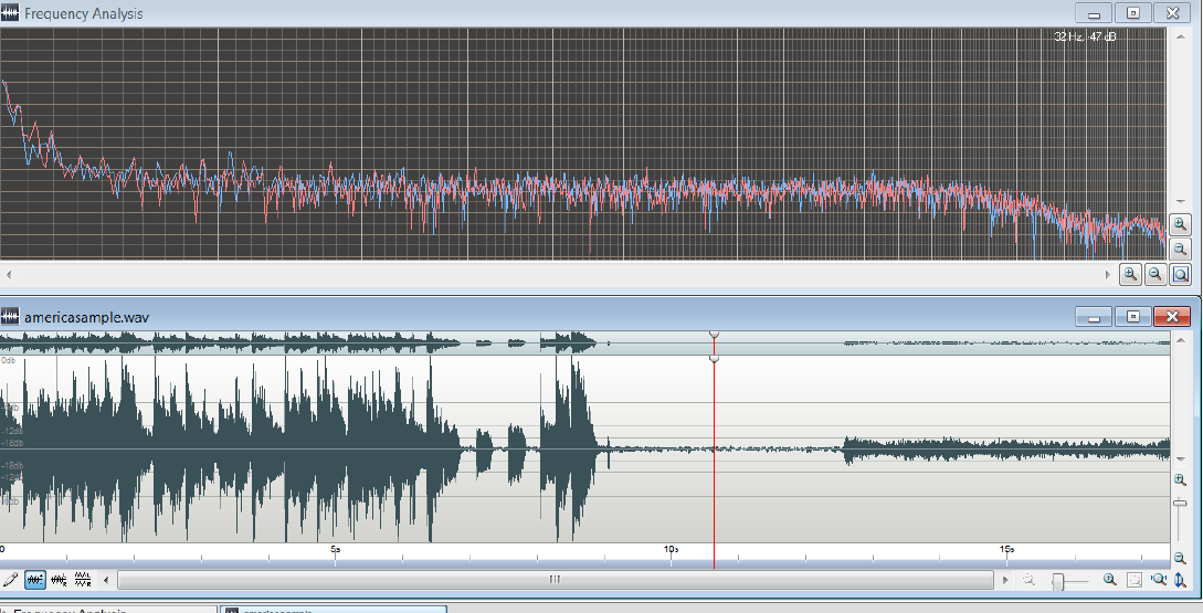
Below is a sample taken from my new Technics of the same passage. It shows a slight rumble here.
Good luck to all you who want to DIY. Lots of fun.